3D Scan Piping For Ships (And Why It Helps)
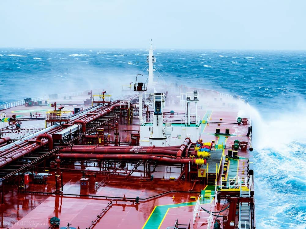
Piping in a ship’s engine room is critical to the many different functions of a ship. If ever there was a case where lives depend on the efficiency of machinery, that case is in the maritime industry. Large cargo ships cruise the world over, and not only the lives of crews but increasingly oceanic ecosystems can be impacted by poor machinery.
A 3D scan of piping in a ship’s engine room can create effective and accurate models of the engine room’s pipe systems, including identifying parts that may fail. These records can also be used for:
- A ship’s inspections
- A reference for repairs
- A reference for complicated installations and retrofits
If a ship needs maintenance in port or a problem occurs at sea, the ship’s engineer needs accurate measurements of the engine room at his disposal. This article will discuss the effectiveness of 3D scanning over traditional methods and how a 3D scan can be used to benefit repairs, problem identification, and retrofits.
3D Scanning In An Engine Room
A 3D scan is accomplished using laser technology to measure out precise points and distances in any given area. For engine room applications, a 3D laser scanner would be one of two types:
- Time-of-flight scanner
- Phase-shift scanner
Time-of-Flight laser scanners use the speed of light to measure differences in distances from the laser point to the scanner, while phase-shift scanners use changes in the laser’s pulse to determine those distances.
Both styles of laser scanners are mounted on a tripod and can scan an area of up to 300 meters (phase-shift scanners) or up to 1000 meters (time-of-flight scanners). Both scanners use a swiveling mirror to direct the laser in a 360-degree area.
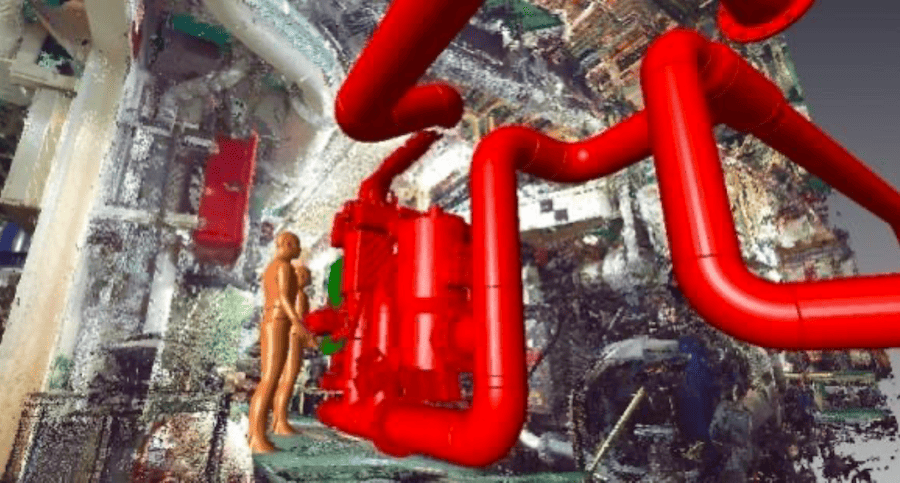
Scanners create what is called cloud point data, a collection of all the single points that the laser scans. That information can then be used to develop a CAD model to reference the area that was scanned.
The Model
The scanner collects the raw data, but it takes a second step for a technician to create a CAD model using a host of modeling software. Once you have this model, you can use it for:
- Presentations
- Diagnostic information
- Maintenance information
Because both scanning and the dissemination of the point cloud data is complicated and takes training to understand, some people go with a service that does these things. Their technicians are trained at setting up scans for complicated areas. They are also trained in assembling that data into a model.
3D Scan Compared To Traditional Measuring
This is one area where you could use that old come-back because there truly is no comparison. Piping systems in ships are very complex under the best of circumstances, even if they were installed using standard practices.
But if pipes were installed under less-than-ideal circumstances with installation practices that include a make-it-fit and map-it-later mentality, that can make a ship’s systems even more difficult to measure.
It could take a long time for an individual with a tape measure to create an accurate plan of piping systems. Even then, hand-done measurements contain a degree of error that could lead to the wrong conclusion. An area might be mistaken as too small for a part when, in reality, the part could fit, or vice versa.
To be sure, a laser scanner still needs a levelheaded technician to identify areas of heavy paint or rust that may throw off measurements. But even so, a 3D scanner in the hands of a qualified technician is going to shave countless hours off the process, as well as follow up visits to remeasure or correctly measure an area.
3D Scan Compared With Original Blueprints
With the blueprints in hand, you may think that you already know where everything is and what the measurements are. Perhaps you even have archived measurements from past inspections. Blueprints are important resources, but they are dated.
Blueprints relate to the way the vessel was made or the way the vessel is supposed to be, not necessarily the way it is now. A ship that has been around for many years has likely seen its share of retrofits and repairs, some done in the yard, some done out at sea. Fabrications have been made that have not necessarily been recorded.
Even the United States Navy has found this to be true. In 2018 it was reported that the Navy saved almost 2 million dollars during a retrofit on the USS George Washington by using scanners to identify problem areas that were not evident at first.
The important thing to note is that 3D laser scanners can accurately pinpoint what might be hidden to the man with the tape measure. Furthermore, the point cloud data and the CAM model that result from the scan are easy to read, display, and understand.
Inspections
One way in which scanning is immediately useful for piping systems in the engine room of a ship is for scheduled inspections and maintenance. If a ship has a scanner and a technician available on the crew, then collecting data for inspections can become a much faster process. Of course, this might be true even if you use a service.
3D scanners can be used to check pipes and the fittings and valves connected to the pipes for defects. A knowledgeable technician can create settings for the scanner with regards factors related to the pipes:
- Material
- Pressure
- Flow stress
Additionally, a technician can check joints and bends of pipes, particularly elbows and Y-sections. 3D scans can evaluate stress on these sections and determine if they are solid or need to be replaced.
There are a lot of advantages to doing it this way. A technician can usually complete a comprehensive scan while the ship is in normal operation. A 3D scan has very few drawbacks, sensitivity to vibration being one of them.
The Need For Accurate Records
If a technician does repeated scans of an engine room, the engineer can have the benefit of a library of records and detailed, usable CAD models of the engine room and its piping. This bank of records is very useful should a problem occur when the ship is at sea.
One problem that may occur in an engine room is flooding. Flooding is likely to be the result of three factors:
- Leaking equipment
- Leaking overboard valve
- Leaking hull
In all cases, documentation and CAD models from a scan could prove vital in speeding up the resolution of any of these problems.
Leaking Equipment
There are many pieces of equipment in an engine room that could leak, from a seawater pump to a boiler. Pipes running into the engine room carrying seawater or freshwater can also be the source of the leak.
Having accurate information on the complicated arrangement of equipment and pipes servicing that equipment can help speed the process of finding the source of the leak. Also, having a detailed schematic helps the engineer identify the appropriate inlet and outlet valves to close to shut off water to the source.
Finally, having that schematic can show the best route toward fabricating a way to stop the leak. An onboard library of records can also be beneficial in tracing down the maintenance history.
Leaking Overboard Valve
Overboard valves keep seawater from coming into the engine room in the event of rough seas or a storm. If an overboard valve does not seal properly, then flooding could occur in the engine room.
Once again, a maintenance history from a highly detailed scan could help identify the leak more quickly if the scan had pinpointed areas of weakness in any of the valves.
Leaking Hull
3D scans can be used on the hulls of ships as well, either during construction or afterward. Scans can capture and analyze angles of the hull to determine areas that need to be changed (during the manufacturing process) or areas that need to be addressed for future maintenance.
When water is leaking into an engine room, certain things will likely be ruled out first, such as:
- Equipment
- Pipes
- Overboard valves
If they are, then having records of a hull scan may help identify the leak, especially if weak areas were noted by the scan for future repairs.
Identifying Corrosion
Corrosion is one of the biggest factors that cause pipes to fail. A 3D scan can help identify corrosion by measuring the thickness of a pipe’s metal and identifying those areas that are weaker than others.
Corrosion can occur from both within the pipe and at the exterior of it, and causes can include atmospheric impact. Here are some of the different types of corrosion that 3D scanning can pick up in pipes within a ship’s engine room.
Uniform Corrosion
The most common form of corrosion is uniform corrosion, and it looks just like the name. It is often found in pipes that carry saltwater, including pipes leading to ballast tanks (which will be discussed later in the article). Some factors that determine how bad uniform corrosion is are:
- Relative humidity
- Temperature
- Oxygen content
- Salt content
One of the ways to determine whether or not a pipe needs to be replaced due to uniform corrosion is by measurement. A 3D scan can accurately determine if the corroded area is larger than in the previous scan or close to the thickness of the pipe.
Pitting Corrosion
Again, the name is like the condition. Pitting corrosion results in the formation of random and localized pits, particularly when the protective film of the pipe breaks down. Pitting corrosion usually occurs in stagnant areas of piping.
Because the pits cause deviations in the material of the pipe, even if they are very small, a 3D scan can detect them and alert the ship’s engineer to their progress and whether or not sections need to be replaced.
Erosion And Abrasion
These forces can cause corrosion in pipes that look a lot like pitting corrosion. The only way to determine one from the other is to examine the circumstance surrounding the corrosion.
Erosion and abrasion happen because the force of fluids breakdown the metal of the piping over time. This being the case, this type of corrosion is typically going to happen in areas of the pipe that experience the most force. For example:
- Elbows
- Y-joints
- Valves
- Narrow fittings
Once again, the usefulness of a 3D scan is pretty clear. The scan can determine the location of the wear by measuring the thickness of the pipe. A knowledgeable person can also get the most out of CAD models by knowing where to look.
Other Types of Corrosion
Because the 3D scan collects information from millions of points that are gathered by a laser, it can pinpoint very small details in a highly accurate way. As a result, any type of corrosion can be identified. Here are a few other kinds that can be seen on a 3D scan.
- Fatigue damage – This usually occurs because of some mechanical interference with the pipe. For example, an area where a machine causes a lot of vibration can wear down a pipe until corrosion begins to result.
- Graphite corrosion – This happens because oxidation occurs within the pipe that leaches iron off of the surface. This usually happens where different water flows interact, like at elbows.
- Galvanic corrosion – Galvanic corrosion occurs because of an electro-chemical breakdown where two different metals meet. It is common where pipes connect to machine parts made of different metals.
With all these different types of corrosion, leaking is a possible and likely result if left unattended. Conducting 3D scans with normal inspections gives ship engineers the chance to identify problems before they have negative ramifications.
Usefulness Of The 3D Scan In Retrofitting
Obtaining 3D scans of the ship’s pipes in the engine room can be beneficial in other ways as well. There are times when ships will need to be retrofitted with new equipment. Having an accurate model of the current piping system can help engineers determine how to modify that system for the installation of the equipment.
As awareness increases on the impact that shipping has on ocean environments, regulations are beginning to address equipment in ships directly related to that impact. There are two areas in particular where ships are having to install equipment in order to lessen the negative impact on oceanic ecosystems:
- Ballast water
- Sulfur in engine exhaust
Ballast Water
Ballast water is an important issue in the maritime industry as it relates to oceanic ecosystems. Sometime between loading and unloading cargo in a port, a large ship will take on fresh or seawater and use that water in the upcoming voyage to stabilize the ship. It is called ballast water.
The problem for ecology and marine life is that when the ship gets to its destination, it will dump the ballast water, effectively transporting the bacteria and small marine life from one ecosystem into another, creating the potential for that ecosystem to be overrun by foreign bacteria.
Shipping companies are now having to retrofit treatment tanks into their ships that essentially clean the water that is taken on as ballast so that when it is dumped, it will not introduce foreign marine into the ecosystem.
A 3D scan of a ship’s engine room can provide a vital piece in the workflow of installing one of these tanks. Because it is a new piece of equipment, the tank has to be fit into the existing network of pipes that manage the flow of ballast water. This is a big project. A 3D scan provides highly detailed information for the planning and execution.
Scrubber Exhaust Gas Cleaning Systems
The International Maritime Organization instituted a global sulfur cap in 2020 for shipping. The exhaust from ships can now only put out a very small percentage of sulfur. The trade-off is that with the scrubber installed, ships can consume cheaper fuel that is high in sulfur.
The scrubber system comes in different types:
- Open-loop
- Closed-loop
- Hybrid
An open-loop scrubber takes in seawater and uses it to scrub the exhaust before cleaning the seawater and dumping it back out into the ocean. A closed-loop system uses freshwater that is chemically engineered to mimic the neutralizing effect of saltwater. A hybrid system is a combination of the two.
Having a 3D scan of the engine room’s piping will enable engineers to be able to retrofit the complicated scrubber system. With a large job like this, having all the information before you begin it is essential. Running into unexpected obstacles or unforeseen circumstances only makes an expensive job more expensive.
Conclusion
Perhaps you have heard the saying, Work smarter, not harder. Keeping up with the maintenance of a ship can be hard work. There are many parts in an engine room that can fail and need to be checked regularly to avoid something breaking at the worst time. And retrofitting requires accurate information.
3D scanning helps you work smarter. When you have a 3D scan before you begin a long and costly retrofit, you are assured that all the available information is at your disposal in a way that is clear to understand and communicate with others. And having scans done regularly helps you keep track of the ship’s systems and when they may fail.
Contact us
Whether you just have a small question or want to get a customized offer from us:
Contact us now.
We are happy to help you.